During an interesting QSO on 70cm in February 2026, a subject arose between VK4JMF (John) and VK4CPS (Paul). As the conversation was of a general nature, a GPSD locking system radio failed on one of the radios, which bought up the subject on a method to use when calibrating your transceiver mainly older radios. Within a few minutes in, others had entered the QSO, one radio with a 10MHz reference attached making the QSO total controlled by the RIT (Receive Increment Tuning). Hence the following methods:
Some operators have been having issues when calibrating your transceiver mainly older radios radio’s to decode beacons and digital software. Some of the older brands have TCXO’s, some adjustable, newer SDR models such as (Icom IC7300,7610,9700 etc., Elecraft K series) will include High Resolution local Oscillator, some have 10Mhz reference input, which offers a varying degree of stability. Brands also offer self-aligning with the introduction of a carrier frequency.
Other’s like Yaesu FT series have a +/-0.5PPM High Resolution DDS/PLL local Oscillator included as part of the standard package. Although most HF users would not be limited by any slight shifting frequency in their day-to-day SSB/AM and digital work (FT8, WSPR etc), maybe timing on the PC software only.
Will all this is great for the above framework a small issue arises with 2/70/23 cm and above (Microwave frequencies) as 10mHz references are great, they are a momentary solution when using digital software like WSJT-X (JT4,Q65 etc), for weak signal work. A lot has been written and products have been built to offer great results here:
Our primary task here is to offer and easy way to align your radio with all the above knowledge. Please feel free to offer other ways.
1. Depending on your signal source ie. local beacon or portable, say 70cm.
2. Turn VFO to 432.440Mhz (This being local to the writer)
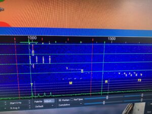
3. run WSJT-X, adjust CPU timing. Note your Frequency.
4. Adjust the TCXO to read 1000MHz on the waterfall.
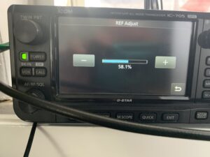
adjustment IC705
5. Happy Days
Also another valued offering, bought too lite by an older Club member (VK4GHZ), as follows:
- Normal CW Mode
- Your radio offsets the receive frequency by the sidetone pitch (e.g., 600–800 Hz) from the actual carrier.
- If you tune to a station in CW mode, you’re hearing the tone created by that offset.
- Reverse CW Mode
- Switching to CW-R changes the offset direction.
- If you’re exactly on the station’s carrier frequency, the tone pitch will be the same in both CW and CW-R.
- If the pitch changes, you’re slightly off frequency.
- Proving Frequency
- Tune until the tone pitch is identical in both CW and CW-R.
- At that point, your displayed frequency matches the station’s actual carrier frequency (within your rig’s accuracy).